The principle of a photocoupler can be simply understood as a photoelectric switch, which consists of a light-emitting diode (emitting light signals) and a receiving diode (receiving light signals).
First, since it transmits optical signals, its primary function is electrical isolation. This type of optocoupler is known as the transistor output optocoupler. It is widely used in:
Ground loop elimination
Interface between logic circuits
Level conversion
Regulation feedback circuits in switching mode power supplies (SMPS)
And more
Typical Circuit Diagram:

Most Widely Used Models:
Typical Circuit Diagram:
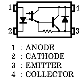
Most Widely Used Models:
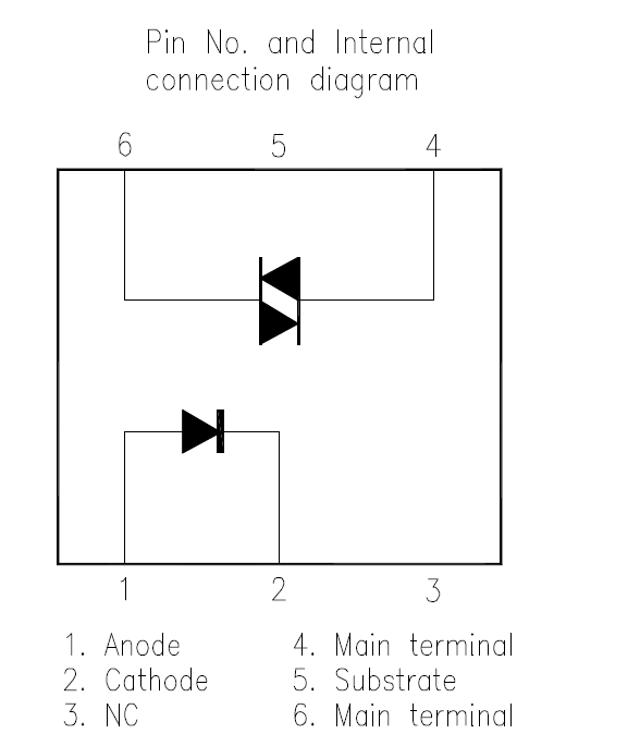
Most Commonly Used Model:
Fourth, by using a high-speed response photosensitive element instead of the receiving diode, we achieve fast and frequent switching, making it suitable for high-speed digital signal transmission. This type of optocoupler is the high-speed optocoupler. It is widely used in:
High-voltage isolation
Isolation of line receivers
Ground loop elimination
Feedback elements in switching power supplies
Typical Circuit Diagram:
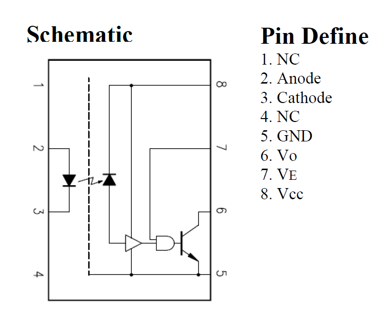
Most Commonly Used Model:
Fifth, by integrating additional components into the receiving diode to provide functions such as undervoltage lockout and short-circuit protection, we obtain the IGBT drive optocoupler. It is widely used in:
IGBT/MOSFET gate drive
Uninterruptible power supplies (UPS)
Industrial inverters
Motor drives
Induction cookers
Typical Circuit Diagram:
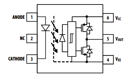
Most Commonly Used Model:
Sixth, by combining the Darlington optocoupler with the thyristor optocoupler, we achieve an optocoupler relay that features a fast, high-gain input and an output capable of driving large current loads. This optocoupler relay structure includes an LED, a photosensitive component (such as a phototransistor, photosensitive SCR, or photosensitive Triac), and a power output switch (such as a MOSFET or Triac). It is widely used in:
AC motor drives and starters
Electromagnetic contactors
Solenoid valve/valve control
Solid-state relays
Static power switches
Temperature control
Typical Circuit Diagram:
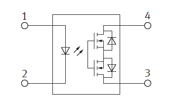
Most Commonly Used Model:
The above is the principle and function of each detailed classification of the current optocoupler.
HI, have you found that each classification is like a building block, by changing something, you can get a product with another purpose.
Knowledge is so rich and simple.
Yes, ECsimple talks about the key points. This is our original intention: knowledge is simple and easy to understand.
The essence of optocoupler is the transmission of optical signals. By replacing the input and output ends or adding input and output ends, many types or functions of optocouplers can be derived.

Most Widely Used Models:
| Model | Brand | Encapsulation | Typical parameters |
|---|---|---|---|
| 4N25 | Vishay, Lite-On, Fairchild | DIP-6 | CTR: 20% - 50%, Max Isolation Voltage: 5,000 VRMS, Operating Temperature Range: -55°C to +100°C |
| PC817 | Sharp, Everlight, Vishay | DIP-4 | CTR: 50% - 600%, Max Isolation Voltage: 5,000 VRMS, Operating Temperature Range: -30°C to +100°C |
| TLP521 | Toshiba, Vishay | DIP-4 | CTR: 50% - 600%, Max Isolation Voltage: 5,000 VRMS, Operating Temperature Range: -30°C to +100°C |
| H11A1 | Fairchild, ON Semiconductor | DIP-6 | CTR: 20% - 200%, Max Isolation Voltage: 5,000 VRMS, Operating Temperature Range: -55°C to +100°C |
| CNY17 | Vishay, Lite-On | DIP-6 | CTR: 40% - 320%, Max Isolation Voltage: 5,000 VRMS, Operating Temperature Range: -55°C to +100°C |
| H11B1 | Fairchild, ON Semiconductor | DIP-6 | CTR: 20% - 300%, Max Isolation Voltage: 5,300 VRMS, Operating Temperature Range: -55°C to +100°C |
| LTV-817 | Lite-On | DIP-4 | CTR: 50% - 600%, Max Isolation Voltage: 5,000 VRMS, Operating Temperature Range: -30°C to +100°C |
| SFH6106 | Vishay | DIP-4 | CTR: 40% - 320%, Max Isolation Voltage: 5,000 VRMS, Operating Temperature Range: -55°C to +100°C |
| H11L1 | ON Semiconductor | DIP-6 | CTR: 10% - 30%, Max Isolation Voltage: 5,300 VRMS, Operating Temperature Range: -55°C to +100°C |
| 4N32 | Vishay, Lite-On | DIP-6 | CTR: 20% - 200%, Max Isolation Voltage: 5,300 VRMS, Operating Temperature Range: -55°C to +100°C |
Second, by adding a power transistor to the transmitting diode, we significantly improve the current transfer ratio (CTR). This type of optocoupler is called the Darlington output optocoupler. It is widely used in:
Hybrid substrates requiring high-density installation
Telephones
Copiers
Fax machines
Interfaces with various power circuits and distribution boards
Hybrid substrates requiring high-density installation
Telephones
Copiers
Fax machines
Interfaces with various power circuits and distribution boards
Typical Circuit Diagram:

Most Widely Used Models:
| Model | Brand | Encapsulation | Typical parameters |
|---|---|---|---|
| LTV-352T | Lite-On | SOP-4 | OPTOISO 3.75KV DARLINGTON 4SOP |
| TLP187 | Toshiba | SOP-4 | X36 PB-F PHOTOCOUPLER ROHS SO6 B |
| EL452(TA)-G | Everlight | SOP-6 | CTR: 1000% - 2000%, Max Isolation Voltage: 5,000 VRMS, Operating Temperature Range: -30°C to +100°C |
| LTV-852 | Lite-On | DIP-4 | OPTOISOLTR 5KV DARLINGTON 4-DIP |
| TIL113M | ON Semiconductor | DIP-6 | OPTOISO 4.17KV DARL W/BASE 6DIP |
| PS2502-1 | Renesas | DIP-4 | OPTOISOLATOR 5KV DARL 4DIP |
| LTV-852 | Lite-On | DIP-4 | OPTOISOLTR 5KV DARLINGTON 4-DIP |
| TLP127 | Toshiba | SOP-4 | OPTOISOLTR 2.5KV DARLNG 6-MFSOP |
| TCMD4000 | Vishay | DIP-6 | OPTOISO 3.75KV 4CH DARLNG 16-SOP |
| KPC452 | COSMO | DIP-6 | CTR: 1000% , Max Isolation Voltage: 5,300 VRMS, Operating Temperature Range: -55°C to +100°C |
Third, by replacing the receiving diode with a thyristor or bidirectional thyristor, we can directly drive high-current loads and handle AC signals. This type of optocoupler is the thyristor output photocoupler. It is widely used in:
AC motor drivers
AC motor starters
Electromagnetic contactors
Lighting control
Solenoid valve/valve control
Solid-state relays
Static power switches
Temperature control
Typical Circuit Diagram:
AC motor drivers
AC motor starters
Electromagnetic contactors
Lighting control
Solenoid valve/valve control
Solid-state relays
Static power switches
Temperature control
Typical Circuit Diagram:

Most Commonly Used Model:
| Model | Brand | Encapsulation | Typical parameters |
|---|---|---|---|
| MOC3021 | Lite-On,Vishay,ON Semiconductor.Everlight | DIP-6 | Non-zero crossing optocoupler with a maximum on-state current of 15mA.Withstand voltage: 400V. |
| MOC3022 |
Lite-On,Vishay,ON Semiconductor.Everlight | DIP-4 | Non-zero crossing optocoupler with a maximum on-state current of 10mA.Withstand voltage: 400V. |
| MOC3023 | Lite-On,Vishay,ON Semiconductor.Everlight | DIP-4 | Non-zero crossing optocoupler with a maximum on-state current of 5mA.Withstand voltage: 400V. |
| MOC3020 | Lite-On,Vishay,ON Semiconductor.Everlight | DIP-6 | Non-zero crossing optocoupler with a maximum on-state current of 30mA.Withstand voltage: 400V. |
| MOC3063 | Lite-On,Vishay,ON Semiconductor.Everlight | DIP-6 | Zero-crossing optocoupler with a maximum on-state current of 5mA and a withstand voltage of 600V. |
| MOC3052 | Fairchild, ON Semiconductor | DIP-6 | Non-zero crossing optocoupler with a maximum on-state current of 10mA.Withstand voltage: 600V. |
| MOC3083 | Lite-On,Vishay,ON Semiconductor.Everlight | DIP-4 | Zero-crossing optocoupler with a maximum on-state current of 5mA and a withstand voltage of 800V. |
| MOC3043 | Lite-On,Vishay,ON Semiconductor.Everlight | DIP-4 | Zero-crossing optocoupler with a maximum on-state current of 5mA and a withstand voltage of 400V. |
| MOC3061 | Lite-On,Vishay,ON Semiconductor.Everlight | DIP-6 | Zero-crossing optocoupler with a maximum on-state current of 15mA and a withstand voltage of 600V. |
| MOC3062 | Lite-On,Vishay,ON Semiconductor.Everlight | DIP-6 | Zero-crossing optocoupler with a maximum on-state current of 10mA and a withstand voltage of 600V. |
Fourth, by using a high-speed response photosensitive element instead of the receiving diode, we achieve fast and frequent switching, making it suitable for high-speed digital signal transmission. This type of optocoupler is the high-speed optocoupler. It is widely used in:
High-voltage isolation
Isolation of line receivers
Ground loop elimination
Feedback elements in switching power supplies
Typical Circuit Diagram:

Most Commonly Used Model:
| Model | Brand | Encapsulation | Typical parameters |
|---|---|---|---|
| 6N135 | Vishay, Lite-On, Fairchild, Everlight | DIP-8 | HIGH SPEED 1Mbit/s TRANSISTOR,Minimum CTR: 7% |
| 6N136 | Vishay, Lite-On, Fairchild, Everlight | DIP-8 | HIGH SPEED 1Mbit/s TRANSISTOR,Minimum CTR: 19% |
| 6N137 | Vishay, Lite-On, Fairchild, Everlight | DIP-8 | HIGH SPEED 10Mbit/s TRANSISTOR,Minimum CTR: 7% |
| 6N138 | Vishay, Lite-On, Fairchild, Everlight | DIP-8 | HIGH SPEED 100 kBd TRANSISTOR,Minimum CTR: 400% |
| 6N139 | Vishay, Lite-On, Fairchild, Everlight | DIP-8 | HIGH SPEED 100 kBd TRANSISTOR,Minimum CTR: 500% |
| HCPL2630 | Broadcom,AVAGO,Onsemi | DIP-8 | Dual Channel,HIGH SPEED 10Mbit/s TRANSISTOR |
| HCPL2631 | Broadcom,AVAGO,Onsemi | DIP-8 | Dual Channel,HIGH SPEED 10Mbit/s TRANSISTOR |
| TLP152 | TOSHIBA | DIP-4 | OPTOISO 3.75KV GATE DRIVER 6SO-5 |
| TLP109 | TOSHIBA | SOP-5 | OPTOISO 3.75KV GATE DRIVER 6SO-5 |
| HCPL0601 | Broadcom,AVAGO,Onsemi | SOP-8 | Single Channel,HIGH SPEED 10Mbit/s TRANSISTOR,Small size |
Fifth, by integrating additional components into the receiving diode to provide functions such as undervoltage lockout and short-circuit protection, we obtain the IGBT drive optocoupler. It is widely used in:
IGBT/MOSFET gate drive
Uninterruptible power supplies (UPS)
Industrial inverters
Motor drives
Induction cookers
Typical Circuit Diagram:

Most Commonly Used Model:
| Model | Brand | Encapsulation | Typical parameters |
|---|---|---|---|
| TLP350 | Toshiba | DIP-8 | Buffer logic, ±2.5A output current, ±15 kV/μs immunity. |
| FOD3180 | Fairchild, ON Semiconductor | DIP-8 | 2A output, 200ns delay, 5000Vrms isolation, 15kV/μs anti-interference |
| ACPL-330J | Toshiba | SOP-16 | 1.5A output, 250ns delay, 50kV/μs anti-interference, UVLO protection. |
| FOD8316 | Fairchild, ON Semiconductor | SOP-16 | 35kV/μs anti-interference, 2.5A output, 250ns delay, UVLO protection, 15-30V voltage range. |
| ACPL-W341 | Broadcom/AVAGO |
SOP-6 | 3A output, 200ns delay, 35kV/μs anti-interference, UVLO protection, 15-30V voltage range |
| ACPL-K33T | Broadcom/AVAGO |
SOP-8 | 2A output, 120ns delay, 50kV/μs anti-interference, -40°C to +125°C temperature range, UVLO protection |
| TLP5702 | Toshiba | SOP-6 | ±2.5A output, 200ns delay, ±30kV/μs anti-interference, -40 to 110°C temperature range |
| ACPL-32JT | Broadcom/AVAGO |
SOP-16 | 2.5A output, 250ns delay, 20V regulation voltage, -40 to +125°C temperature range, 30kV/μs anti-interference |
| ACPL-339J | Broadcom/AVAGO |
SOP-16 | 1A output, 300ns delay, 25kV/μs anti-interference, -40 to 105°C temperature range, UVLO protection |
| HCPL-7710 | Broadcom/AVAGO |
DIP-8 | +5V CMOS compatible, 40ns delay, 12 Mbd speed, 10kV/μs glitch immunity, -40°C to 100°C temperature range |
Sixth, by combining the Darlington optocoupler with the thyristor optocoupler, we achieve an optocoupler relay that features a fast, high-gain input and an output capable of driving large current loads. This optocoupler relay structure includes an LED, a photosensitive component (such as a phototransistor, photosensitive SCR, or photosensitive Triac), and a power output switch (such as a MOSFET or Triac). It is widely used in:
AC motor drives and starters
Electromagnetic contactors
Solenoid valve/valve control
Solid-state relays
Static power switches
Temperature control
Typical Circuit Diagram:

Most Commonly Used Model:
| Model | Brand | Encapsulation | Typical parameters |
|---|---|---|---|
| AQY210 | Panasonic | DIP-4,SMD4,SOP4 | 1 Form A, AC/DC dual use, 350V, 120MA low level analog signal control, maximum leakage current 1μA |
| AQY212 | Panasonic | DIP-4,SMD4,SOP4 | 1 Form A, AC/DC dual use, 60V, 500MA low level analog signal control, maximum leakage current 1μA |
| AQY214 | Panasonic | DIP-4,SMD4,SOP4 | 1 Form A, AC/DC dual use, 400V, 100MA low level analog signal control, maximum leakage current 1μA |
| AQY216 | Panasonic | DIP-4,SMD4,SOP4 | 1 Form A, AC/DC dual use, 600V, 120MA low level analog signal control, maximum leakage current 1μA |
| AQY414 | Panasonic | DIP-4,SMD4,SOP4 | 1 Form B, 400V, 120MA, low on-resistance, low leakage current, maximum control of 0.55A load current. |
| AQY410 | Panasonic | DIP-4,SMD4,SOP4 | 1 Form B, 350V, 130MA, low on-resistance, low leakage current, maximum control of 0.55A load current. |
| AQY412 | Panasonic | DIP-4,SMD4,SOP4 | 1 Form B, 60V, 550MA, low on-resistance, low leakage current, maximum control of 0.55A load current. |
| AQW610 | Panasonic | DIP-8,SMD8,SOP8 | 1 Form A & 1 Form B, 350 V, 100 mA, 0.45A high capacity, low on-resistance (typically 12Ω), control low-level analog signals, maximum leakage current 1μA |
| AQW612 | Panasonic | DIP-8,SMD8,SOP8 | 1 Form A & 1 Form B, 60 V, 450 mA, 0.45A high capacity, low on-resistance (typically 12Ω), control low-level analog signals, maximum leakage current 1μA |
| AQW614 | Panasonic | DIP-8,SMD8,SOP8 | 1 Form A & 1 Form B, 400 V, 130 mA, 0.45A high capacity, low on-resistance (typically 12Ω), control low-level analog signals, maximum leakage current 1μA |
The above is the principle and function of each detailed classification of the current optocoupler.
HI, have you found that each classification is like a building block, by changing something, you can get a product with another purpose.
Knowledge is so rich and simple.
Yes, ECsimple talks about the key points. This is our original intention: knowledge is simple and easy to understand.
The essence of optocoupler is the transmission of optical signals. By replacing the input and output ends or adding input and output ends, many types or functions of optocouplers can be derived.